With the Hackspace having a collection of three different 3D printers and with them all being kept in one multi use workshop, it soon came apparent that we needed a way to keep the dust of of them all whiles also allowing us to gain easy access to them for maintenance. There was an ideal place in the workshop between the workbench and tool board where a cabinet would sit nicely.
With this in mind I took some measurements of the area and make a few rough sketches on paper. The cabinet would be 1200 x 600 x 2000 it would be divided up in to 6 quadrants, the top 4 quadrants will be where the 3D printers would be housed and the bottom two would
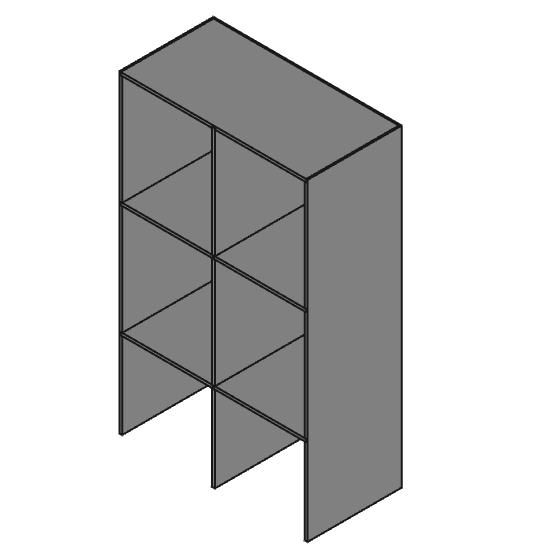
3D model of the cabinet
create storage space for reels of filament and other consumables. At the rear of each of the 4 printer quadrants there would be a 2G plug and RJ45 socket as each of the printers will run of OctoPi allowing the printers to be controlled remotely on the network. Once I had a feel for what the cabinet was going to look like on paper I drew up a 3D model using Free CAD.
The material of choice was 18mm construction ply, for the method of joinery I went for rebate joints. Each of the panels that the shelf’s and back would sit in had a rebate grove in the width of the ply routed down the width of the panel at the corresponding heights of the shelf’s the rebate was half the depth of the material. The cut away below shows half of the cabinet and how it is assembled. With the CAD design complete I got to work ripping all of the ply down to size ready for routing.
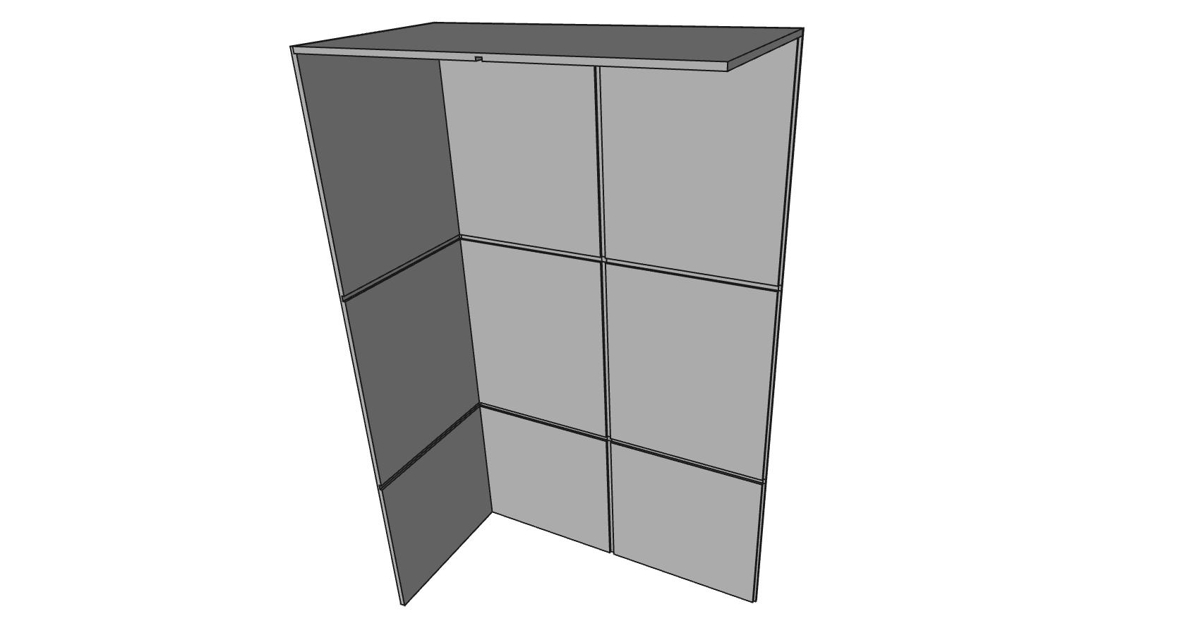 Cut away of the cabinet showing the rebate joints
To ensure that all of the rebates where routed consistently I used a straight edge to guide the router on all the parts. By scoring each side of the rebate joints with a sharp knife before routing prevents tear out from the spinning cutter leaving a nicer and smoother finish. For routing the rebate on the perimeter of the back the router was used with it’s fens, the fens was set to the correct width from the cutter to the edge of the work piece and run down the edge.
To assemble the cabinet the shelf’s where first glued and nailed on to the two sides, this step was completed first because you could only get a run of nails in one side of the middle. The middle and top where then joined the same way followed by the back. After a sand and coat of varnish the cabinet was ready to be moved in to the workshop.
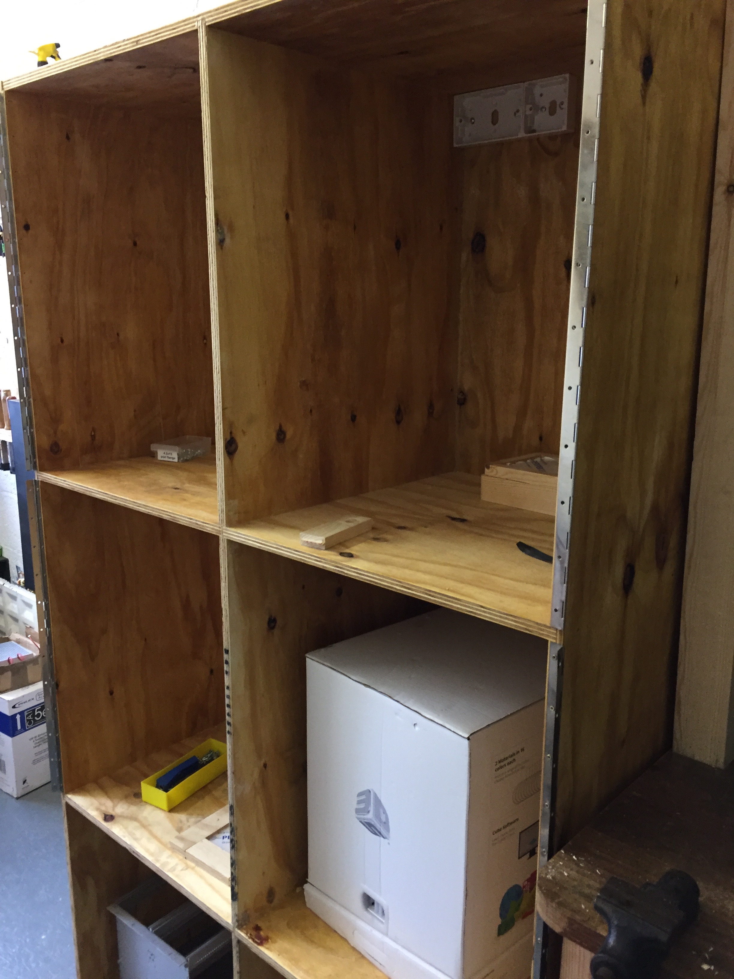
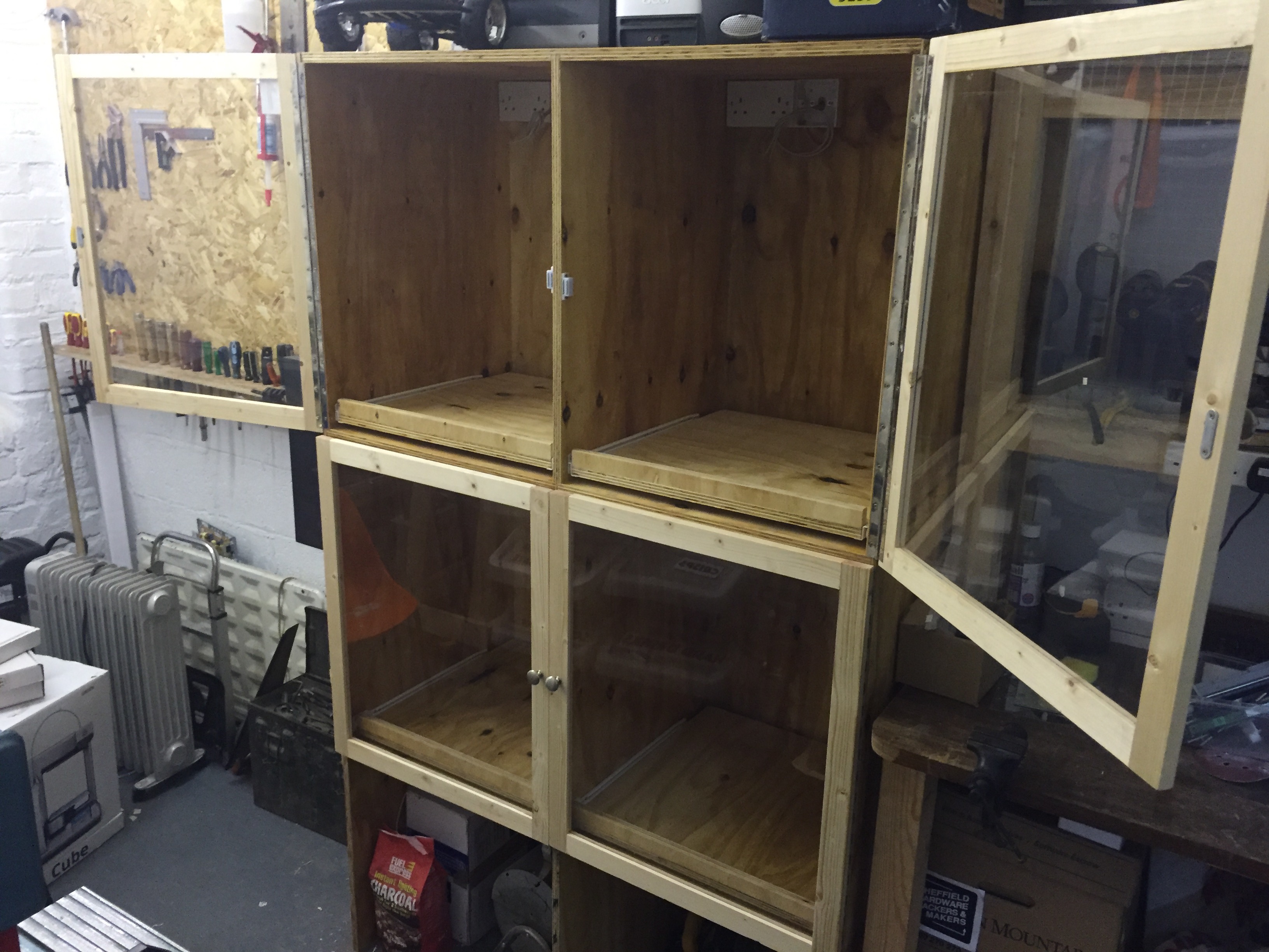
The assembled cabinet in place ready for the doors to be hung.
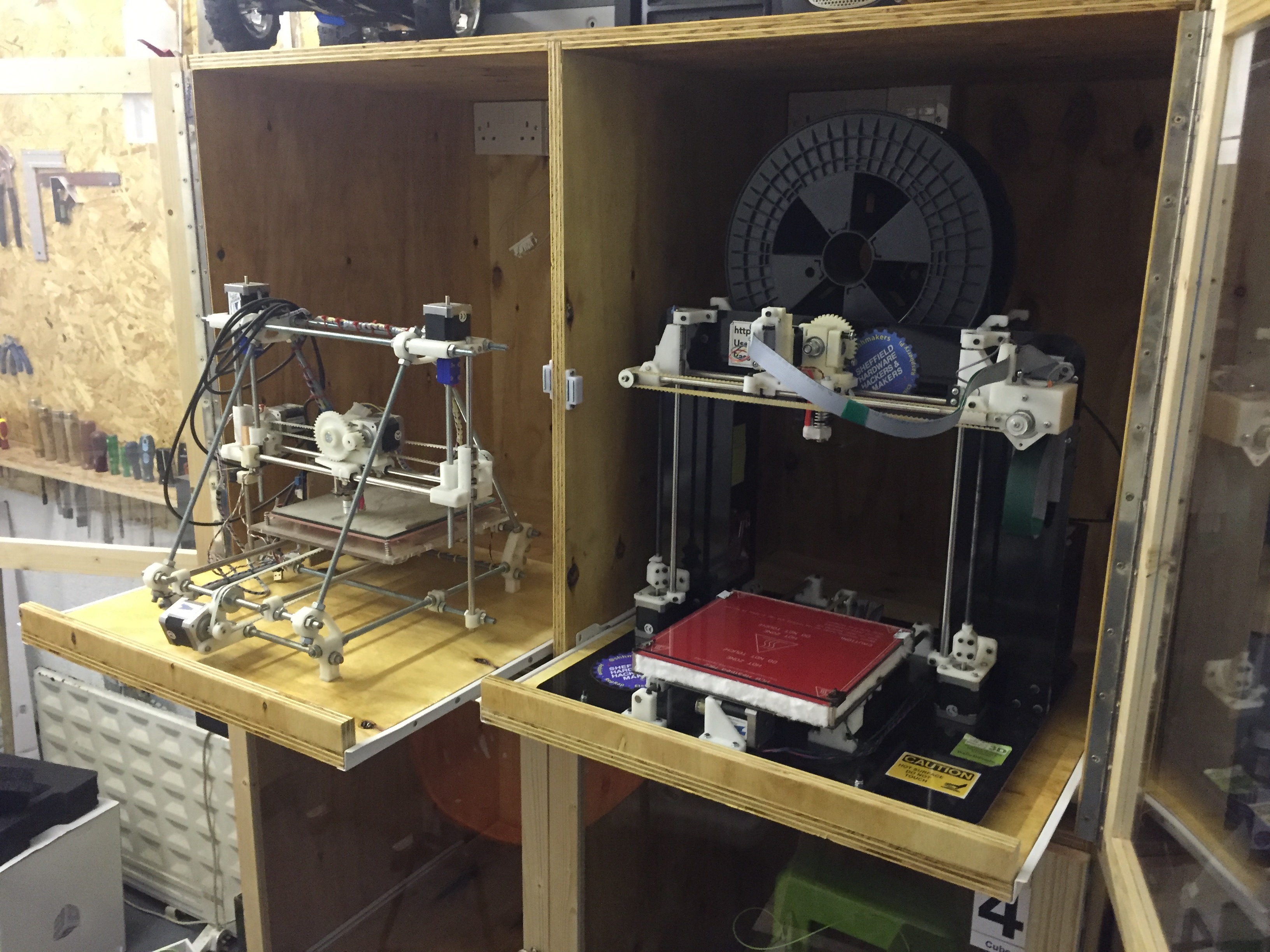
Once the assembly was complete I decided to add some pull out shelf’s on rails, this would make it easier to remove things from the print bed and gain access to the back of the printer for maintenance.
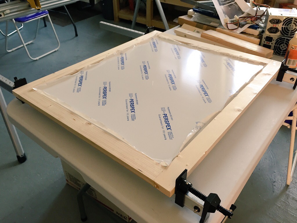
door frame glued up
To make the door frames I created a central groove using a table saw in several lengths of 20 x 35mm PSE timber. This grove would be where the perspex in the centre of the door would sit. The rails and stiles where cut to the correct length and a tenon was made on the end of both of the horizontal rails. The perspex sheet was cut to size and the frame was glued up using a pair of sash clamps. I used piano hinge to hang the doors, this was mounted on to the cabinet first.
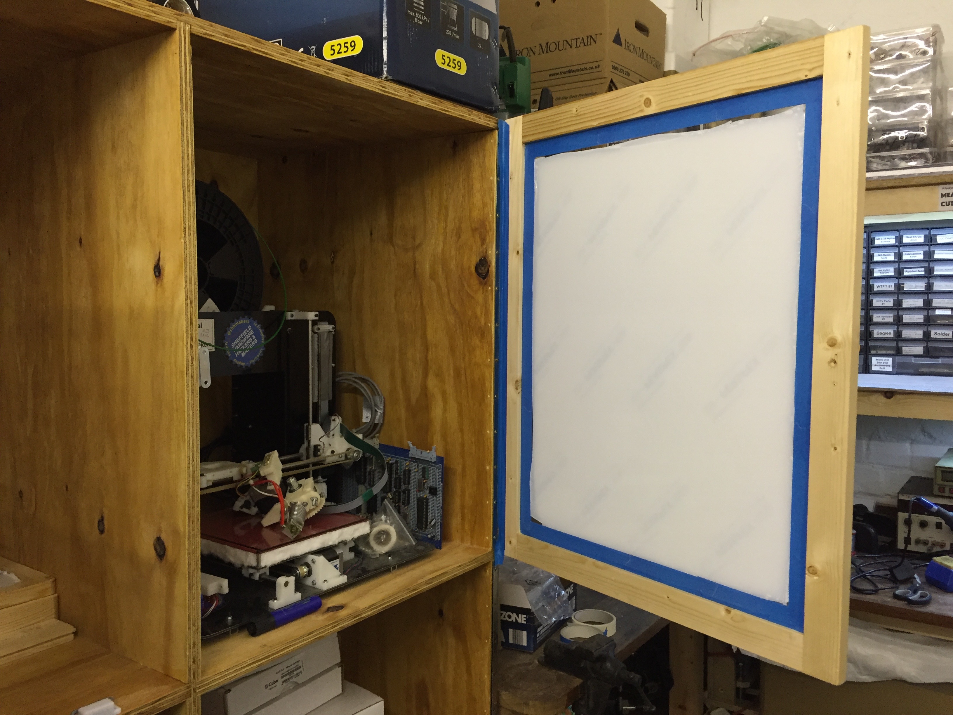 The first door mounted
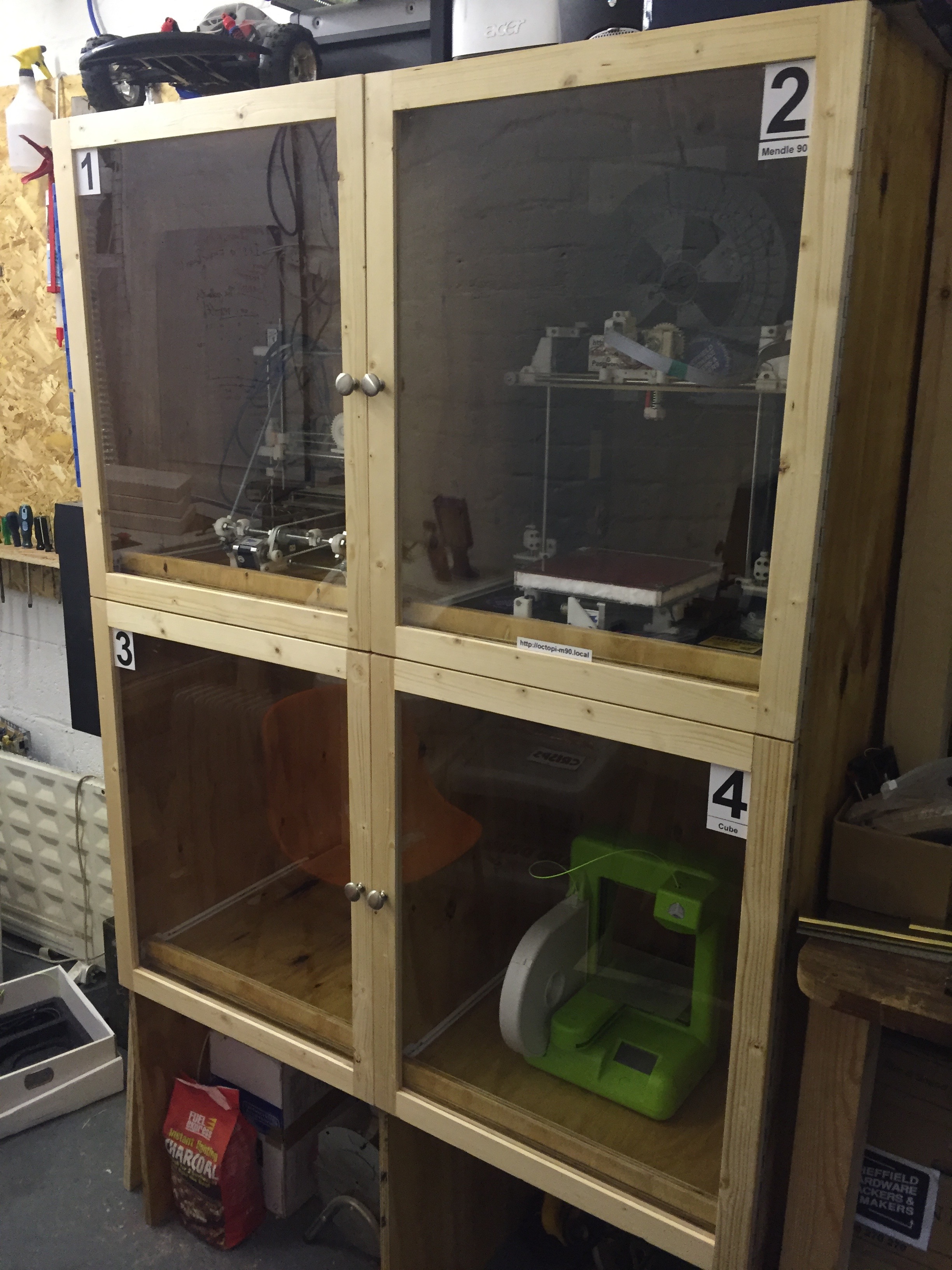
All that was left to do now was install the rest of the doors, give them a coat of varnish, wire in the electrics and mount the pull out shelves. With the 3D printer cabinet approaching completion there where a few things that I could have done differently and some things that could be improved or even added on. One thing that could be different is the method of joinery, there are a multitude of different ways that it cold be done the other witch I looked in to was finger joints. Finer joints provide a larger surface area for glue to stick to but are more time consuming. I ended up using rebate joints because they where more suited to the design, not only that but would also give me more experience for the next job where I could attempt something a little more complex with the skills I have learnt.
Something else that would have helped during the build process is to have made a jig that could be set over the rebate and clamped down that the router would sit in and slide across, making the process of routing the rebates much more efficient and accurate quicker. A later addition that I intend on adding is a set of castor boxes for the bottom two quadrants witch will make it easier to retrieve consumables. Overall it has been a fairly successfully build. The cabinet itself is very sturdy and provides the purpose it was intended for it also provides more storage areas both on top of the cabinet and down below in the two quadrants.
For more images please visit here.