By Richard M Langner
This article describes how you can use an Arduino UNO to program a bare ATtiny85 micro-controller chip. I will show you how to program the ATtiny85 with the ‘Blink’ sketch. These are the steps –
- Connect the UNO to the ATtiny breadboard and connect the 10uF capacitor
- Configure the Arduino as an In-circuit Serial Programmer (ISP)
- Insert the ATtiny85 into the breadboard
- Configure the IDE for the ATtiny85
- Modify and upload the ‘blink’ sketch to the ATtiny85
1. Connect the UNO to the ATtiny85 breadboard and connect the 10uF capacitor
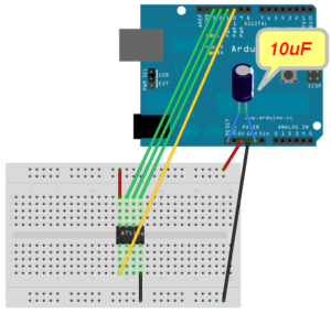
Connect the UNO to the breadboard as shown below. If you intended to keep the breadboard and UNO solely for programming, I recommend using an 8 pin socket for the ATtiny85 – this will ensure you insert the chip in the correct place each time on the breadboard.
Don’t insert the ATtiny85 in the socket yet – you must first configure the UNO to act as a programmer.
Pin connections:
- ATtiny Pin 2 to Arduino Pin 13
- ATtiny Pin 1 to Arduino Pin 12
- ATtiny Pin 0 to Arduino Pin 11
- ATtiny Reset Pin to Arduino Pin 10
- ATtiny Pin 2 to 150Ω resistor, resistor to LED anode, LED cathode to GND (not shown here).
- 10uF capacitor connects between GND (-) and RESET (+)
2. Configure the Arduino as an In-circuit Serial Programmer (ISP)
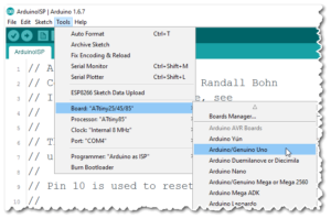
Select the Arduino UNO board
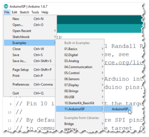
and open the ISP sketch.
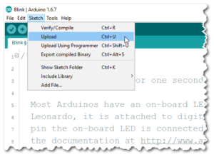
Next you should upload the ISP example to the UNO board. Ensure you have selected the correct COM port.
Congratulations! Your UNO is configured as a programmer.
You’re now ready to program the ATtiny85 with the ‘Blink’ sketch. You will need to connect an LED to display the blink. Connect a 150 Ohm resistor to the physical pin2 on the chip. The other end of the resistor should connect to the LED anode (its long leg), and the LED cathode connects to GND.
3. Insert the ATtiny85 into the breadboard
Remove the power by unplugging the USB cable. Taking care, insert the ATtiny chip into the breadboard socket the correct way around. Re-connect the USB cable.
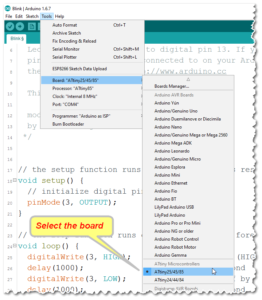
4. Configure the IDE for the ATtiny85
Configure the IDE as follows –
- Board = ATtiny85
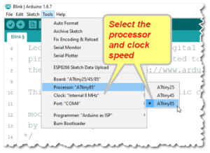
- Processor = ATtiny85
- Clock speed = 8MHz
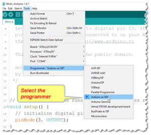
Set the programmer ‘Arduino as ISP’
If the ATtiny85 is new, it will require the fuses to be set. Among other things, fuses set the CPU speed. The fuses only need to be set once for each chip. To do this, select the ‘Burn bootloader’ option.

5. Modify and upload the ‘blink’ sketch to the ATtiny85
Open the example sketch ‘Blink’ and change the LED’s digital pin number to 3 on all the sketch lines (this is because the ATtiny85 does not have a pin13. Note that physical pin2 on the chip is digital pin3 on the ATtiny85). The code should look like this –
// the setup function runs once when you press reset or power the board
void setup() {
  // initialize digital pin 3 as an output.
  pinMode(<strong>3</strong>, OUTPUT);
}

// the loop function runs over and over again forever
void loop() {
  digitalWrite(<strong>3</strong>, HIGH);   // turn the LED on (HIGH is the voltage level)
  delay(1000);              // wait for a second
  digitalWrite(<strong>3</strong>, LOW);    // turn the LED off by making the voltage LOW
  delay(1000);              // wait for a second
}
Finally upload the ‘Blink’ sketch to the ATtiny85.
That’s it! The blink program should now flash the LED.
The UNO is now set up as a programmer and so further ATtiny85 chips may be programmed by simply plugging them into the breadboard and uploading your code to them.
Richard Langner
With thanks to OJ for his help in defining the procedure.
This is my first post here, so please let me know if there is anything missing or incorrect.