How to cut a hole to mate up with what’s inside your project box.
THE PROBLEM — You’ve made the electronics part of your project, and now need to cut a hole in your project box so you can plug in the USB cable. But how do you know where to cut? Unless the box is transparent, you can’t see exactly where the USB socket hole should be. There is a short (2:40) video of this post here.
Update: At the bottom of this post, there are links showing how to locate drill centres WITHOUT any tools.
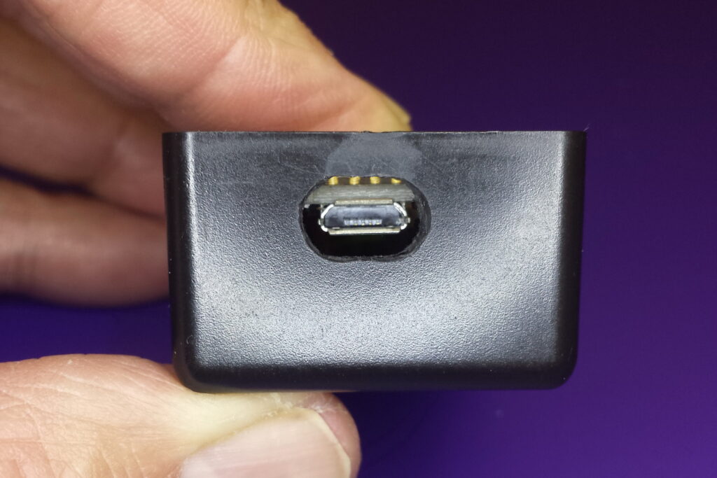 Hole is in exactly the right place. and allows for plug housing
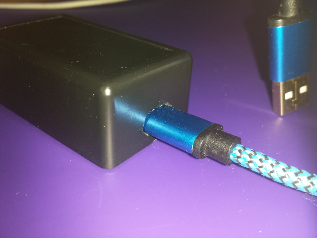 Micro USB plug fits neatly
The usual way is to measure the internal position of the USB socket when the PCB is fully in the box (not always possible) and transfer the measurements to the outside of the box. You have to be able measure and mark accurately.
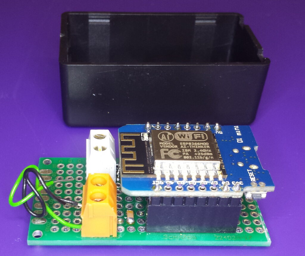 PCB ready to fit into the project box.
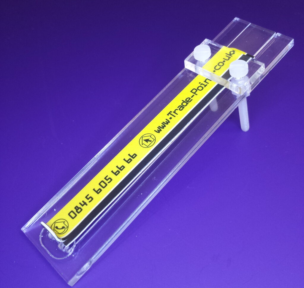
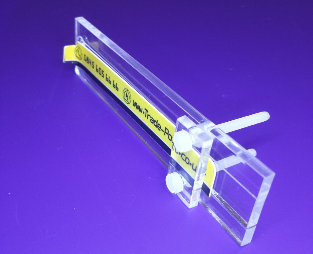
This little tool provides a drilling and cutting guide on the outside of the box, when the USB socket is on the inside of the box (possibly hidden from view). No measuring is required.
 Align the two strips
My design is quite simple. Overlay two strips and fix them together at one end – similar to tweezers. The strips staddle the wall of the project box, one strip inside the box, the other outside. The inner strip is fixed into the USB socket, and the outer strip has guide marks for the required opening.
 Thin yellow inner strip is clamped in position.
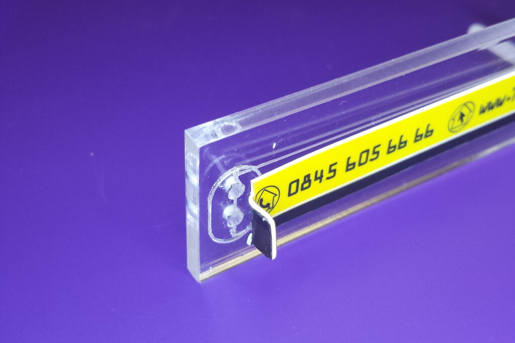
The inner strip — should be reasonably thin so it can fit between the PCB and the box. I cut a 10mm wide strip off an old credit card, narrowed it at one end to make a tab that fits snugly into the USB socket, then bent the tab 90 degrees (warming helps but is not essential).
 Line up the outer strip’s tab with the drill holes.
The outer strip — should be stiff transparent material. At one end, mark where the cut-lines and drill holes should be for the USB socket. Align the inner strip’s tab with the outer strip’s markings, then fasten them together at the other end. That’s it!
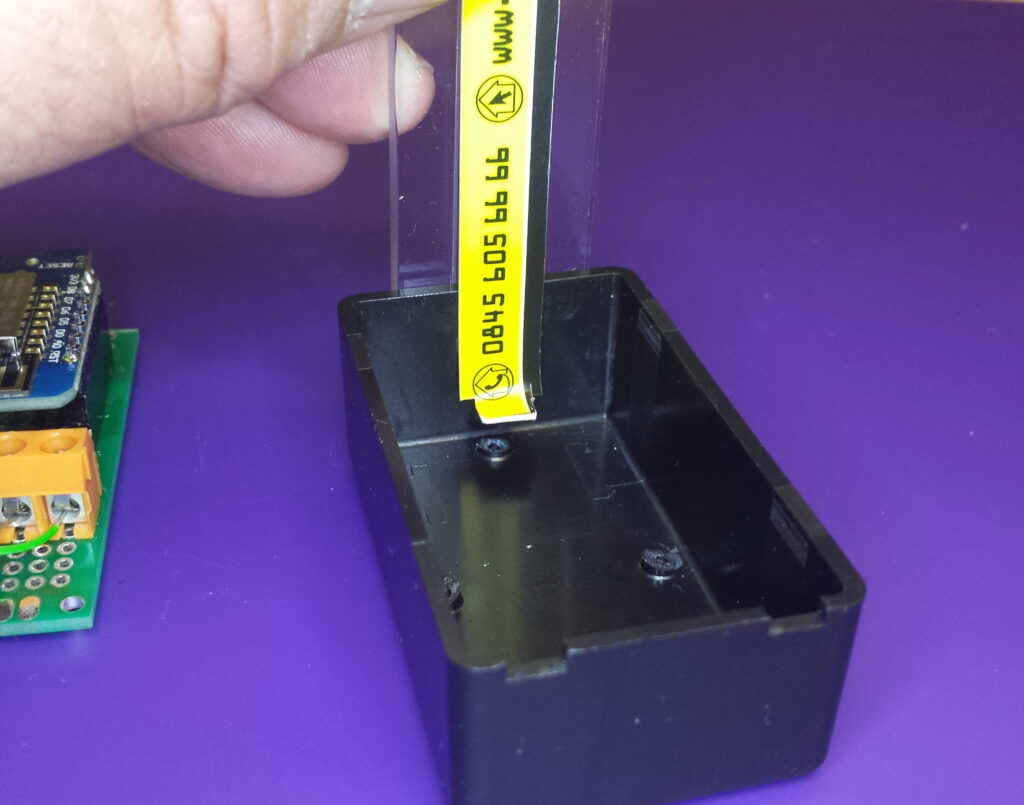
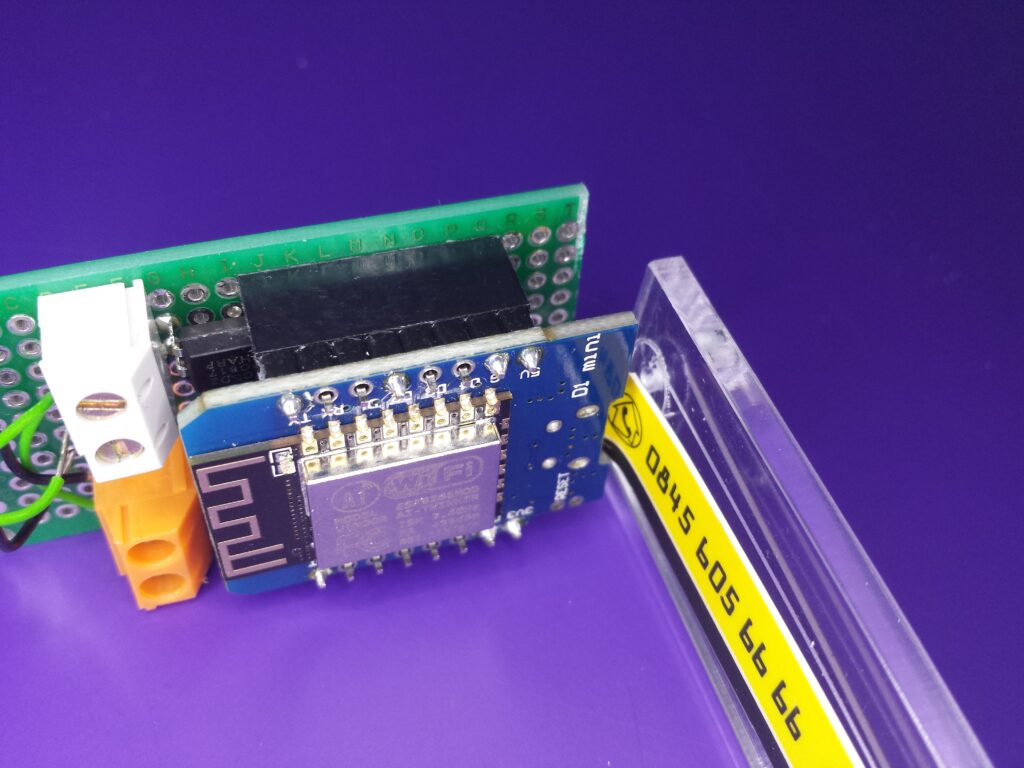 Fit tab into the USB socket
USAGE — To use the template, insert the tab into the USB socket and slide the circuit board and the inner strip into the box. Ensure the outer strip is flat to the outside of the box and use the cutting guides to mark the box. My original marks were the drill-centres for a couple of 6mm holes. Use a drill press for accuracy, and a small file to smooth and adjust the drilled holes to the final shape.
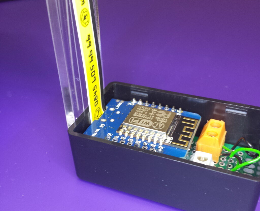
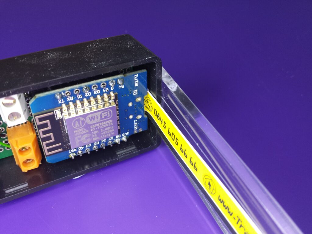 Slide the PCB and the tool into the project box.
 Mark through the drill pilot holes
This technique will work on plastic or metal, and can be adapted for any shape of socket and hole. Draw the marking guide to accept the largest plug you may use.
 View of how it looks on the inside.
CONCLUSION —
Cutting holes in the right place is something I have always struggled with. I have to admit I was amazed when this worked first time!
 Alternative view
Credit goes to Alan Bailey for helping implement this project from concept to completion in just a few hours. Below areYouTube links showing how it’s done, and how to locate holes WITHOUT any tools.