This post by SHH&M member Steve
During the early discussions about our new space at Portland Works we decided it would be good to have an RfID access system, and that this would communicate with a server over the network. This immediately sparked my interest as I had recently taken delivery of some new modules that I had been dying to have a play with, the ESP8266-01.
The ESP8266 is a chip that enables wifi access, with communication over a simple UART (serial) connection. The main selling point of this chip is that it is very low cost compared to other Wifi solutions, typically £2-3 per module. Another huge advantage is its ability to act as a standalone microcontroller – more on that later….
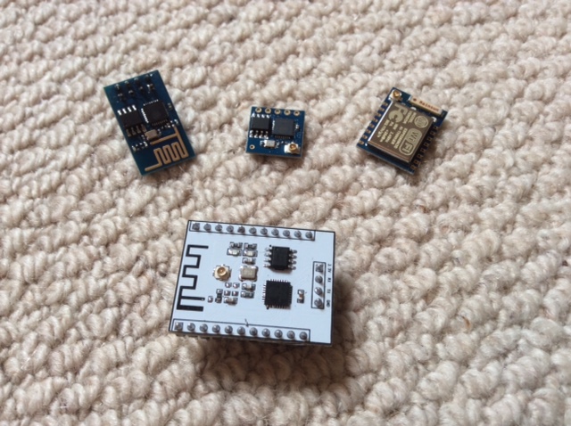
It is available now in quite a few different module sizes depending on how many GPIO (general purpose input / output) pins you need for your project.
The board I used for this project is the 01 module which breaks out only two of the GPIO pins, but as I was connecting it to an Arduino which had far more GPIO available this wasn’t a problem. A pin out for the module can been seen below.
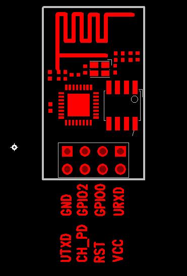
Connecting the module to the Arduino is very simple, with one classic “gotcha”. The ESP8266 module runs on 3.3 volts and is not 5 volt compliant meaning that if you are using a standard 5v Arduino board you will need to make sure the voltages sent to the board do not exceed 3.3 volts. This is actually pretty easy as there are so few connections. Vcc can be connected to the 3.3v output on the Arduino, as can CH_PD (I soldered a 10k resistor between Vcc and CH_PD you can do whatever is easiest), and GND can be connected to GND. Tx from the ESP8266 to Rx on the Arduino can be directly connected since the Arduino will read a voltage of 3.3v as high. Connecting Rx on the ESP8266 to Tx on the Arduino is the one that needs care since the Arduino will be outputting 5v. There are many ways to do this, the simplest being a voltage divider which will work fine at lower baud rates (9600 is the default on the more up to date firmware), or you could use a level shifting circuit. To avoid some of this messing, and to be absolutely certain of not frying your module, you could always use a 3.3v Arduino or convert an existing one using this guide…
https://learn.adafruit.com/arduino-tips-tricks-and-techniques/3-3v-conversion
It is possible to connect the ESP8266 directly to a USB to serial converter. Personally I had mixed results with this method. While it is very easy to connect, ensuring you have a converter that is capable of 3.3v, I found that the converter wasn’t always able to supply the current required for the module, at times in excess of 200ma, which caused brown outs and stability issues.
Now we are ready to talk to the module. If you haven’t already got the Arduino IDE installed head over to arduino.cc and download and install it. If you are working on a raspberry pi open up the command line and type
sudo apt-get install arduino
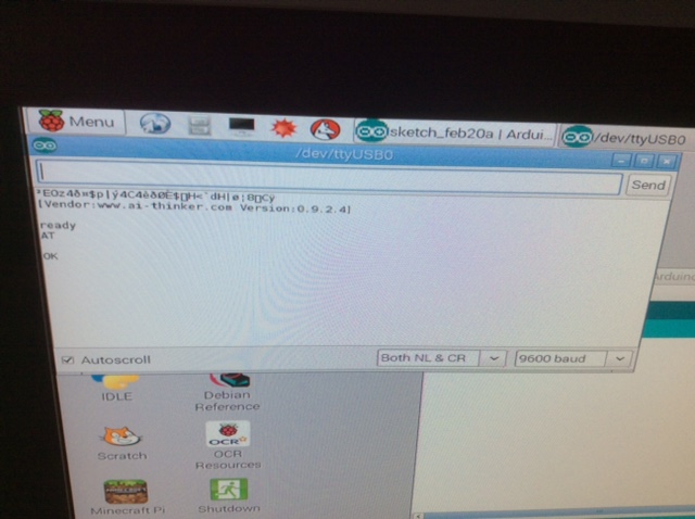
Before trying to connect to the serial port its best to upload a basic sketch to the board, “blink” for example, to ensure whatever is on the board won’t be trying to use the serial port. Once done, open up the serial port interface (icon in the top right corner), set the baud rate to 9600 and the other drop down box to “Both NL & CR”. If the serial port of open before power is connected to the module you should see some nonsense characters (module starting up) followed by the vendor ID and version number. If not, type AT into the text box and either press enter or click send and the module should reply with the word “OK”
A bit of troubleshooting isn’t uncommon at this point. If you don’t see anything at all check that there is a red light on the module and then check the rest of the connections (I’ve missed setting CH_PD high more than once!). Still nothing? Try swapping the Tx and Rx connections on the Arduino as these are easy to mix up. Some versions of the firmware seem to be a little sensitive if GPIO 0 isn’t pulled high so that is also worth trying. If you still aren’t seeing anything, or are getting random characters, try changing the baud rate of the serial monitor. Most of the up to date firmware is set at 9600 but I have had modules set at 115200 and have seen reports of other modules at even more different ones.
Assuming all is well you can now try sending different commands to the module to test it out. The first to try is
AT+RST
This resets the board and when it’s back up you should see the word “ready”. Now let’s connect it to your WiFi. First we need to set the board status as it can act as a device, access point or both, so we are going to set it as a device.
AT+CWMODE=1
Now let’s see if your module can “see” your network.
AT+CWLAP
This takes a few seconds but when done a list of the current networks within range are displayed. Hopefully the one you want to connect to will be among them! The next command will connect the module to your router, just bare in mind that it is case sensitive to you must place capital and lowercase letters in the correct place in both the SSID and password
AT+CWJAP=”yourssid”,”password”
Again this takes a few seconds to get a message back which will confirm a connection or inform you of a failure. This message is usually “OK” or “error” but that does depend on your firmware version. Whatever the message it will be obvious.
You can now talk to any device connected to the internet! Doing this is now straightforward but with so many different things you can do I won’t go into too many details here (I’ve included a list of useful resources at the end of the blog). One thing that took me a while to realise though was that the module has to be set to accept multiple connections before opening up a TCP connection. To do this simply send the command AT+CIPMUX=1 before opening the connection.
I touched earlier on using the additional GPIO instead of an Arduino. To do this you need to be able to run your own code on the ESP8266, as you do on the Arduino, and this means replacing the firmware that is currently installed on the module.
Useful resources …
https://nurdspace.nl/ESP8266#AT_Commands
http://www.electrodragon.com/w/ESP8266
http://www.esp8266.com/wiki/doku.php