Visualise Active Ports
Sometimes it’s useful to know the activity on the GPIO pins of your microcontroller. This little monitor board is designed specifically for the Wemos D1 mini and has a LED on each GPIO pin to help you visualise what is happening on inputs and outputs.
Microcontroller boards other than the D1 mini can be accommodated by either re-designing the layout for the extra pins, or using extension leads to monitor those pins you are interested in.
LEDs can be disconnected by removing the jumper links, so as not to interfere with other functions. All LED series resistors deliberately have a high value to minimise loading the GPIO pins. The white LEDs drew less than 500 microamps each when used with a 1K series resistor, and they were still quite bright.
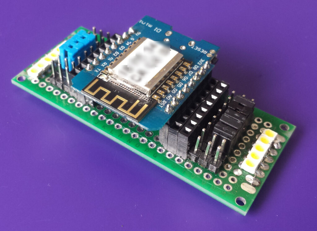 General view showing breakout header sockets, header pins, and jumpers.
The monitor can also act as a small breakout board, extending the Wemos header pins to 2 sockets and 2 pins per GPIO line. This can be handy when developing your project, as Dupont extension leads could be used to connect the monitor board to your PCB.
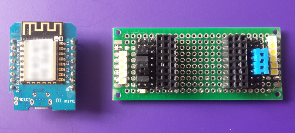 Wemos D1 mini and the breakout test board.
Construction is simple – besides the header pins and sockets, there are just a dozen SMD resistors and LEDs, mounted on a prototyping board. The underside of the board is where the connections were made, linking pins with single strands taken from a length of scrap multistrand wire.
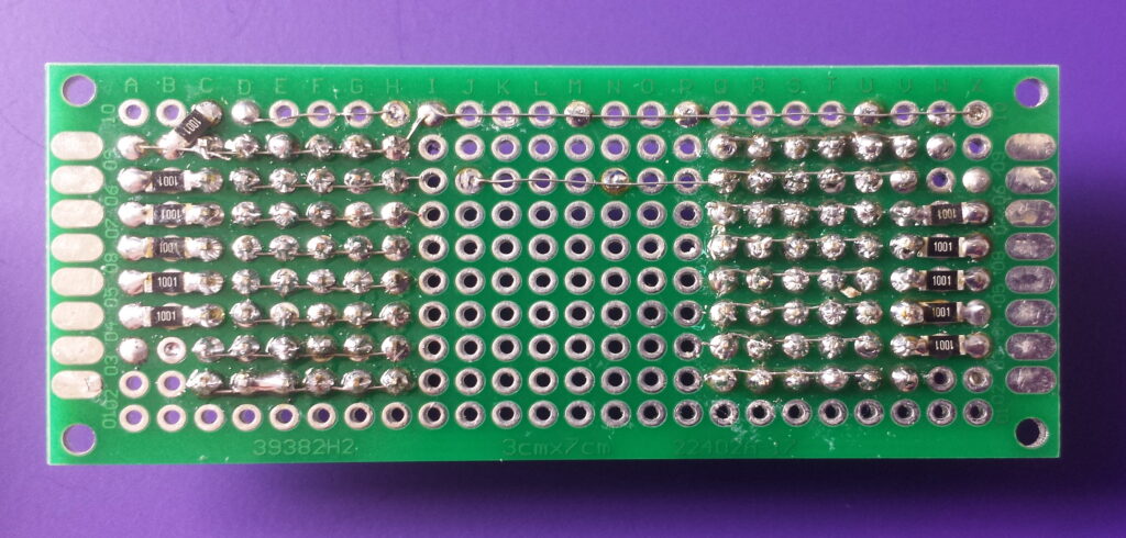 Underside showng the link wires and SMD resistors.
The video shows the board with jumpers installed for all 9 GPIO ports (D0 to D8). Due to high value series resistors, the LEDs do not interfere with program uploading, and if you install the RX and TX jumpers you can watch the LEDs giving a satisfying twinkle with the upload activity.